What's the real story on end-fed antennas?
With an engineering degree, I understand the physics of electricity better than many operators. In fact, my physics teacher (Robert Resnick) is an international legend and co-authored the textbooks that most of the free world used.
That said, I am presenting unbiased information based on facts and over 50 years of experience with radio communications. I haven't gotten any "free stuff" from antenna companies or dealers so have no financial reason to favor or discourage you from any particular design.
There are basically 2 popular kinds of end-fed HF antennas.
End-Fed Half Wave
The EFHW is a resonant wire fed at the end instead of in the middle like a dipole. The length is determined by the lowest frequency desired. This is about 130 feet long for 80m or about 65 feet long for 40m.
A benefit of this antenna is the ability to see low SWR on harmonic bands, typically 40m, 20m, 15m, and 10m with an 80m EFHW. A tuner is rarely needed with a properly tuned resonant antenna. The obvious exception would be for operation in the opposite end of the band for which it was tuned. Of course, you could tune the wire for SSB and have a linkable addition for CW & FT8.
The impedance at the feedpoint end of a resonant wire can be several thousand ohms. To match this load to the 50 ohm transmitter and coax, a transformer of 49:1 (typical) to as high as 81:1 is used. While some wind this "unun" themselves, most purchase it, ranging in cost from $25 to $150 or higher depending on wattage requirements. >picture link<
There are two significant downsides to the EFHW design.
First, safety is compromised as the voltage at the transmitter is multiplied times 7 by the transformer. This will be about 500 volts at 100 watts and 1.9KV at full legal power. People need to be kept well clear of the transformer end of the antenna. Think about the typical Field Day with scout troops wandering around the site. Kids are inquisitive and inclined to touch stuff.
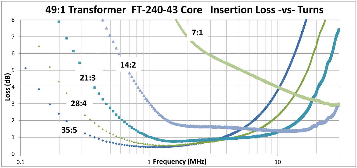
Second, the miniscule voltage coming back down the antenna is divided by 7 before getting to the coax and receiver. While the design benefits from the efficiency of resonance, it loses most of this gain in the transformer. The typical receiver sensitivity of .16 uV is jacked up to 1.3 uV by the transformer. On 20m the loss is about 3dB, basically cutting your signal in HALF. Thanks to AF7NX for the graph below showing loss for different turn ratios. Pay attention to the right side since that's where 20m is.
The resonant wire is bi-directional, so you can point the lobes at stations you want or use the nulls to minimize interference.
Because of the high voltage and for best performance, it is usually recommended that all parts of a 40m EFHW antenna be at least 10 feet above ground and for an 80m EFHW antenna at least 20 feet above ground. Height is might.
End-Fed Long Wire
This design uses a wire length that is specifically chosen to be non-resonant for all bands the antenna is used on. A commonly recommended length is 53 feet. There are many articles on the web that list alternate lengths for various bands.
A benefit of this antenna is manageable SWR over most HF bands, meaning that SWR is low enough for the auto-tuner in many transceivers to work as advertised. It has the added advantage of working on 30m, 17m, 12m bands which are unavailable with most EFHW systems previously described. Note that an external wide-range antenna tuner is sometimes required.
The impedance at the feedpoint end of the wire is typically around 450 ohms. To match this load to the 50 ohm transmitter and coax, a 9:1 transformer is often used. Cost is similar to 49:1 models. >picture link<
The 9:1 transformer has less loss than the 49:1, but this is offset by the inefficiency introduced with the wire being non-resonant. If you don't understand resonance, watch a YouTube video showing an opera singer breaking a glass with her voice. >video link<
The benefit of resonance to efficiency is huge, and this design misses out. In my testing, weak signals which were just strong enough to hear and work with my resonant dipole were completely nonexistent with a non-resonant 53-foot wire and 9:1 transformer.
Michael, KB9VBR, also noticed this when his resonant Wolf River Coil TIA could hear stations better than his non-resonant Chameleon MPAS. The difference on 80m was about 2 S-units or 6 dB. >video link<
You can hear the benefit of resonance yourself with a WRC or SuperAntenna. Just listen to signals get stronger/weaker as you move the slider up and down.
Note that really long wire antennas can benefit from something called "capture area" which simply means that longer wires capture more signals than short ones. There's more copper in the air for electrons to hit. It's that simple.
The non-resonant wire is unidirectional, which can be a blessing or a curse, depending on whether you're trying to get a rare DX station or need omni coverage for POTA.
A common mode choke (aka line isolator) might be required to keep RF away from you and your equipment. Sometimes an "ugly balun" made by coiling a half dozen turns of coax will suffice.
Coax & Radials
With most end-fed antennas, the shield on the coax feedline is often the counterpoise and will radiate as part of the system. Many companies state the minimum recommended coax length for their antenna to work properly. Sometimes, simply changing the length and position of the coax by a few feet can affect performance and SWR considerably. You can see this by setting your analyzer for continuous sweeps and moving the coax around. Many transformers have a "ground" terminal where you can attach a counterpoise. When doing so, this can help remove some of the effects of coax length and position.
Discussion
So, why would you choose a compromised antenna requiring a lossy transformer? That's a good question. When band conditions are favorable to HF operation, strong signals make it through the transformer OK and are workable. The flexibility of being able to operate on any band you want with a single antenna and minimal fidgeting is a huge benefit. You can change bands with ease, letting your auto-tuner do the work. With the EFHW you should not need a tuner.
The downside is being effectively deaf when conditions are poor. Recently (13 May 2022) friends doing POTA had trouble getting the required 10 contacts to be "activated" at a park using an EFHW antenna. By comparison, I was using a full-size resonant quarter wave vertical and ended up with 127 QSOs including Austria, Croatia, Spain, and Wales during my POTA activation.
The solution is obvious! Use your end-fed for simplicity when bands are good, and have something else in your kit for when conditions require it.
CLICK HERE to see the End-Fed Half-Wave I use!
Sources
End-fed antennas, transformers, and relevant info are available from a variety of companies. The following list is for your convenience and is not guaranteed to be complete. I do not endorse or receive a benefit from any of these companies. Listed alphabetically without preference.
• Balun Designs
• Chameleon
• Emergency Amateur Radio Club of Hawaii
• Hy Power Antennas
• MyAntennas
• Nelson Antennas
• NI4L Antennas
• Packtenna
• Palomar Engineers
• Ultimax Antennas
• Vibroplex (Par EndFedz)
Testing
With an antenna analyzer, it is easy to check an unun transformer. Connect the unun to the analyzer with a double-male UHF adapter >like this<. Connect a suitable carbon resistor across the outputs and sweep it with the analyzer. For a 9:1, that's 9 x 50 = 450 ohm resistor. For 49:1, use a 49 x 50 = 2450 ohm (2.45k) resistor. The sweep should display a low SWR over the entire HF spectrum >like this<. When I scanned a possibly defective LDG 49:1 unun I got an unacceptable plot >like this< which showed it was only marginally useful on 15m and above.
Disclaimer
As with all antennas, "your mileage may vary" depending on too many factors and circumstances to enumerate. Experiment! This is what amateur radio is all about. Figuring out what works (and doesn't) is part of the fun. |