Theory:
This antenna is sometimes called a Tuned Transmission Line Trap or T2LT. It is essentially a vertical half-wave dipole. Like a typical dipole, the design includes two quarter wavelength (¼λ) sections except they are arranged one above the other and are end-fed at the bottom instead of side-by-side and fed in the middle like a horizontal or “V” antenna. The trap, usually a simple coil, separates the actual antenna components from the feedline.

Advantages:
• excellent on-air performance
• low radiation angle good for DX
• no lossy transformer required = efficient
• no radials = tiny footprint
• RF energy well out-of-reach = safe
• easy to build with commonly available materials
One disadvantage is the requirement for a support. While a suitable tree limb could easily work in many parks, some operators will need a mast to deploy this antenna.
Construction:
Both antenna sections should be approximately a quarter wavelength (¼λ) long. Use a Dipole Antenna Calculator (or 234/MHz = length in feet) on the band you are designing for. Example: 234 / 28.400 = 8.24 feet (8 feet 3 inches) for the center of the 10m Technician band. Your actual tuned length may vary from this calculation.
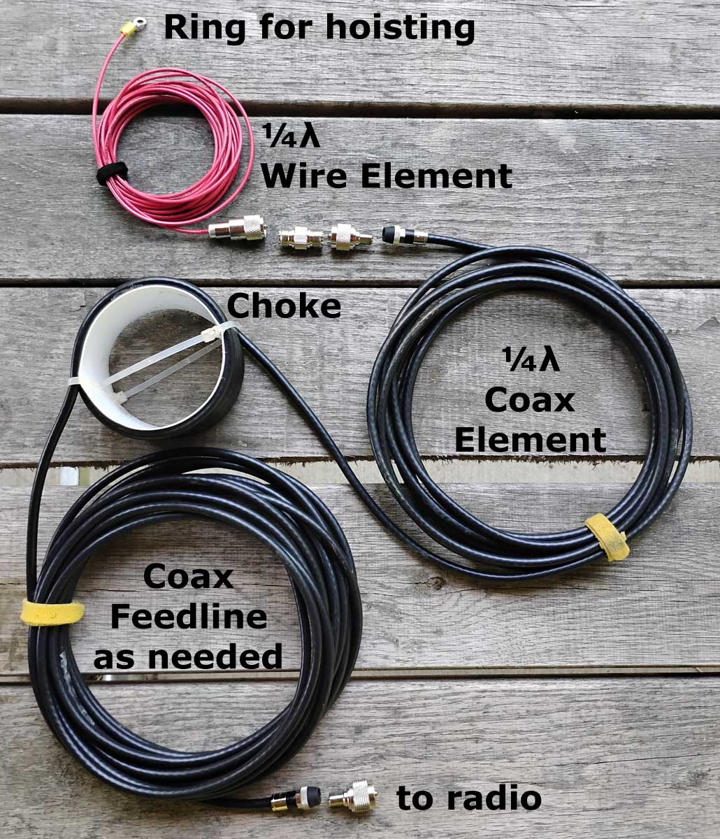
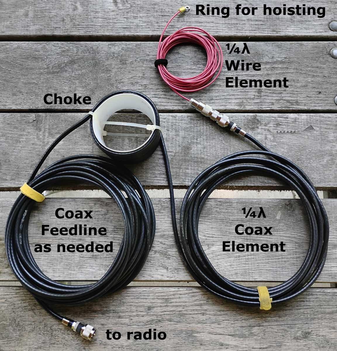
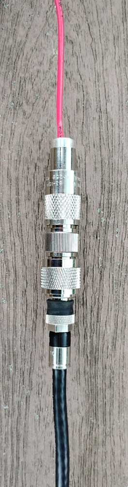
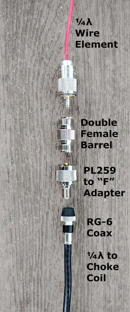
The top half of my T2LT dipole is simply a ¼λ piece of insulated wire. I installed a ring terminal at the top for hoisting via an arborist throw line. The bottom of this wire is connected to the center pin (only) of a standard PL-259 male plug. This plug is then attached to a double-female “barrel” connector.
The bottom half of the T2LT dipole is a ¼λ section of coax (connected to the other side of the barrel) followed by a trap to isolate the antenna from the rest of the coax which serves as a feedline. My T2LT antennas are made using inexpensive RG-58 coax with standard PL-259 plugs on both ends.

The trap can be formed with 8 to 12 turns of coax on a suitable form between 3 and 5 inches in diameter. Some experimentation should be expected, adding or removing turns or moving the coil up or down to find the lowest SWR. The trap should be as high off the ground as possible, ideally ¼λ for best performance, but 6 to 8 feet is sufficient.

Coax Choke aka Trap
sometimes called an “ugly balun”
TIP: an empty plastic peanut butter jar makes a strong and lightweight coil form. I used an empty dietary fiber container. Make small slits one turn in from each end of the form and use nylon cable ties to secure the first and last turn of coax to the form.
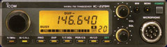
Of course, an analyzer will make tuning easy and precise, but you can use the SWR meter in your rig if you don’t have one.
Performance:
Click map to see QSOs during December 2024 using T2LT antennas

Click the Table to see 109 Countries Contacted

Discussions:
M0MCX
Videos to Watch:
20m version (M0DQW)
20m version (G5TM)
15m version (G5TM)
10m version (G3OJV)
TIP: Since this is a monoband antenna, you may want to make a few of them for your favorite bands.
TIP: Because of the overall height, this antenna is not practical for 30m and lower bands because it would be too long. I can throw my arborist weight over a limb 35 feet up, so that limits my T2LTs to 20m and higher bands.
TIP: The higher you install a T2LT the better, and it helps if the coil is well off the ground. In other words, given a 35 foot support, a 17m T2LT will likely outperform a 20m T2LT because the coil will be 9 feet off the ground instead of just 2 feet.
TIP: You could make this antenna out of 75-ohm CATV coax if that’s what you have. Just add PL-259 to F adapters at both ends of the coax.
|
|
RG6 T2LT Parts |
RG6 T2LT Assembled |
 |
|
RG6 T2LT Connections |
|